Cable Stayed Bridge


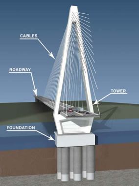
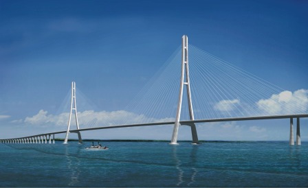
The cable-stayed bridge is related to the cantilever bridge. The cables are in tension, and the deck is in compression. The spans can be constructed as cantilevers until they are joined at the centre. A big difference between cantilever bridges and cable-stayed bridges is that the former usually have a suspended span, and the latter do not.

Cable Stayed Bridge ( Parts )

A cable stayed-bridge lacks the great rigidity of a trussed cantilever, and the continuous beam compensates for this to some extent. Indeed, while a long cable-stayed span is under construction, there may be great concern about possible oscillations, until the cantilevers are joined. For the Pont de Normandie, there was even thought of using active correctors if things threatened to get out of hand. In fact, the construction went smoothly.

The cables are of high tensile steel. In a few examples these are encased in concrete. Towers are often made in concrete, though steel is also used.

Cable Stayed Bridge A

Advantages of cable-stayed bridges

The two halves may be cantilevered out from each side. There is no need for anchorages to sustain strong horizontal forces, because the spans are self-anchoring. They can be cheaper than suspension bridges for a given span. Many asymmetrical designs are possible.

Disadvantages of cable-stayed bridges

In the longer sizes, the cantilevered halves are very susceptible to wind induced oscillation during construction. The cables require careful treatment to protect them from corrosion.


Suspension Bridge


A suspension bridge is a type of bridge in which the deck (the load-bearing portion) is hung below suspension cables on vertical suspenders. The first modern examples of this type of bridge were built in the early 19th century. Simple suspension bridges, which lack vertical suspenders, have a long history in many mountainous parts of the world.

This type of bridge has cables suspended between towers, plus vertical suspender cables that carry the weight of the deck below, upon which traffic crosses. This arrangement allows the deck to be level or to arc upward for additional clearance. Like other suspension bridge types, this type often is constructed without falsework.

Suspension Bridge A

The suspension cables must be anchored at each end of the bridge, since any load applied to the bridge is transformed into a tension in these main cables. The main cables continue beyond the pillars to deck-level supports, and further continue to connections with anchors in the ground. The roadway is supported by vertical suspender cables or rods, called hangers. In some circumstances, the towers may sit on a bluff or canyon edge where the road may proceed directly to the main span, otherwise the bridge will usually have two smaller spans, running between either pair of pillars and the highway, which may be supported by suspender cables or may use a truss bridge to make this connection. In the latter case there will be very little arc in the outboard main cables.

Suspension Bridge B

The main forces in a suspension bridge of any type are tension in the cables and compression in the pillars. Since almost all the force on the pillars is vertically downwards and they are also stabilized by the main cables, the pillars can be made quite slender.

In a suspended deck bridge, cables suspended via towers hold up the road deck. The weight is transferred by the cables to the towers, which in turn transfer the weight to the ground.

Comparison of a catenary and a parabola with the same span and sag

The catenary represents the profile of a simple suspension bridge, or the cable of a suspended-deck suspension bridge on which its deck and hangers have negligible mass compared to its cable. The parabola represents the profile of the cable of a suspended-deck suspension bridge on which its cable and hangers have negligible mass compared to its deck. The profile of the cable of a real suspension bridge with the same span and sag lies between the two curves.

Suspension Bridge Forces

Assuming a negligible weight as compared to the weight of the deck and vehicles being supported, the main cables of a suspension bridge will form a parabola (very similar to a catenary, the form the unloaded cables take before the deck is added). One can see the shape from the constant increase of the gradient of the cable with linear (deck) distance, this increase in gradient at each connection with the deck providing a net upward support force. Combined with the relatively simple constraints placed upon the actual deck, this makes the suspension bridge much simpler to design and analyze than a cable-stayed bridge, where the deck is in compression.


Box Girder Bridges


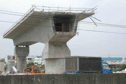
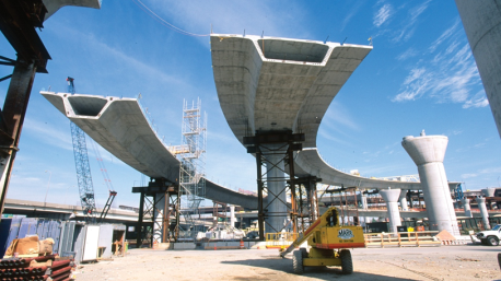
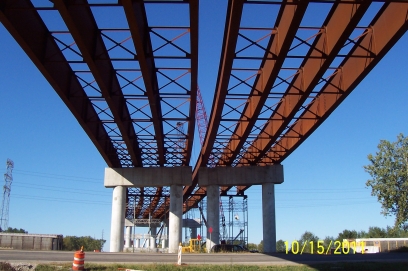
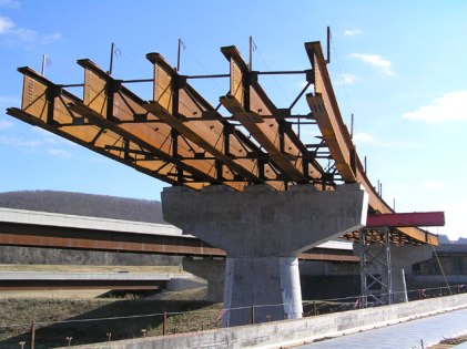
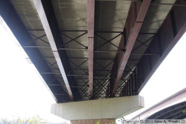
A box girder bridge is a bridge in which the main beams comprise girders in the shape of a hollow box. The box girder normally comprises either prestressed concrete, structural steel, or a composite of steel and reinforced concrete. The box is typically rectangular or trapezoidal in cross-section. Box girder bridges are commonly used for highway flyovers and for modern elevated structures of light rail transport. Although normally the box girder bridge is a form of beam bridge, box girders may also be used on cable-stayed bridges and other forms.

Construction

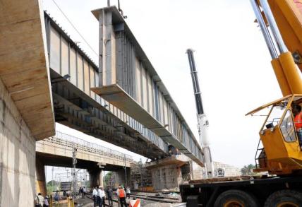
If made of concrete, box girder bridges may be cast in place using falsework supports, removed after completion, or in sections if a segmental bridge. Box girders may also be prefabricated in a fabrication yard, then transported and emplaced using cranes.

For steel box girders, the girders are normally fabricated off site and lifted into place by crane, with sections connected by bolting or welding. If a composite concrete bridge deck is used, it is often cast in-place using temporary falsework supported by the steel girder.

Either form of bridge may also be installed using the technique of incremental launching. Under this method, gantry cranes are often used to place new segments onto the completed portions of the bridge until the bridge superstructure is completed

Box Girder Bridge

Advantages and disadvantages

Compared to I girders, box girders have a number of key advantages and disadvantages. Box girders offer better resistance to torsion, which is particularly of benefit if the bridge deck is curved in plane. Additionally, larger girders can be constructed, because the presence of two webs allows wider and hence stronger flanges to be used. This in turn allows longer spans. On the other hand, box girders are more expensive to fabricate, and they are more difficult to maintain, because of the need for access to a confined space inside the box.

Box Girder Bridge

Corrosion of the steel cables that provide the post-tensioning for box girder bridges has become a major concern. On December 13, 2009, the Indiana Department of Transportation (INDOT) closed the Cline Avenue (SR-912) bridge over the Indiana Harbor and Ship Canal after a routine inspection revealed significant corrosion of the steel tensioning cables and rebar within the box girders due to water seeping through cracks in the bridge deck. After determining the level of corrosion compromised the bridge’s structural integrity beyond repair, INDOT decided to permanently close and eventually demolish the span.


Chemical Admixtures


Chemical admixtures are the ingredients in concrete other than portland cement, water, and aggregate that are added to the mix immediately before or during mixing. Producers use admixtures primarily to reduce the cost of concrete construction; to modify the properties of hardened concrete; to ensure the quality of concrete during mixing, transporting, placing, and curing; and to overcome certain emergencies during concrete operations.

Successful use of admixtures depends on the use of appropriate methods of batching and concreting. Most admixtures are supplied in ready-to-use liquid form and are added to the concrete at the plant or at the jobsite. Certain admixtures, such as pigments, expansive agents, and pumping aids are used only in extremely small amounts and are usually batched by hand from premeasured containers.

The effectiveness of an admixture depends on several factors including: type and amount of cement, water content, mixing time, slump, and temperatures of the concrete and air. Sometimes, effects similar to those achieved through the addition of admixtures can be achieved by altering the concrete mixture-reducing the water-cement ratio, adding additional cement, using a different type of cement, or changing the aggregate and aggregate gradation.

Evaluting Fly Ash for Concrete

Five Functions

Admixtures are classed according to function. There are five distinct classes of chemical admixtures: air-entraining, water-reducing, retarding, accelerating, and plasticizers (superplasticizers). All other varieties of admixtures fall into the specialty category whose functions include corrosion inhibition, shrinkage reduction, alkali-silica reactivity reduction, workability enhancement, bonding, damp proofing, and coloring.

Water-reducing admixtures usually reduce the required water content for a concrete mixture by about 5 to 10 percent. Consequently, concrete containing a water-reducing admixture needs less water to reach a required slump than untreated concrete. The treated concrete can have a lower water-cement ratio. This usually indicates that a higher strength concrete can be produced without increasing the amount of cement. Recent advancements in admixture technology have led to the development of mid-range water reducers. These admixtures reduce water content by at least 8 percent and tend to be more stable over a wider range of temperatures. Mid-range water reducers provide more consistent setting times than standard water reducers.

Retarding admixtures, which slow the setting rate of concrete, are used to counteract the accelerating effect of hot weather on concrete setting. High temperatures often cause an increased rate of hardening which makes placing and finishing difficult. Retarders keep concrete workable during placement and delay the initial set of concrete. Most retarders also function as water reducers and may entrain some air in concrete.

Accelerating admixtures increase the rate of early strength development, reduce the time required for proper curing and protection, and speed up the start of finishing operations. Accelerating admixtures are especially useful for modifying the properties of concrete in cold weather.

Superplasticizers, also known as plasticizers or high-range water reducers (HRWR), reduce water content by 12 to 30 percent and can be added to concrete with a low-to-normal slump and water-cement ratio to make high-slump flowing concrete. Flowing concrete is a highly fluid but workable concrete that can be placed with little or no vibration or compaction. The effect of superplasticizers lasts only 30 to 60 minutes, depending on the brand and dosage rate, and is followed by a rapid loss in workability. As a result of the slump loss, superplasticizers are usually added to concrete at the jobsite.

Corrosion-inhibiting admixtures fall into the specialty admixture category and are used to slow corrosion of reinforcing steel in concrete. Corrosion inhibitors can be used as a defensive strategy for concrete structures, such as marine facilities, highway bridges, and parking garages, that will be exposed to high concentrations of chloride. Other specialty admixtures include shrinkage-reducing admixtures and alkali-silica reactivity inhibitors. The shrinkage reducers are used to control drying shrinkage and minimize cracking, while ASR inhibitors control durability problems associated with alkali-silica reactivity.

Further Reading: Portland Cement Association


Adding Water On-Site


Adding water on-site to concrete mixtures has been a controversial topic for as long as concrete has been used as a construction material. The addition of water is clearly covered in ASTM C94, Standard Specification for Ready Mixed Concrete where it is allowed to adjust fresh concrete properties so the material is suitable for the specific application.

Concrete that is delivered with a low slump may lack the workability for proper placement consolidation and finishing operations. Additionally, low slump concrete mixtures in some cases may be deficient in air content for durability in freezing and thawing environments or where the material may be exposed to deicing chemicals. While on-site additions of water may potentially reduce the final concrete strength properties, in many cases the consequences of adding the water may be less detrimental than attempting to place, consolidate, and finish a concrete mixture that that lacks proper workability and/or air content.

Concrete Pouring

How Much Can I Add?

The general rule is that water may be added to adjust the slump of the material to comply with specifications upon arrival as long as the maximum specified water-cement ratio is not exceeded. Typical additions of water on-site are in the order of one to two gallons per cubic yard of concrete (this would amount to 10 to 20 gallons of water in a 10 cubic yard load). A general rule of thumb for the effect of the addition of water to a concrete mixture is an increase in slump of approximately 1 inch per gallon of water added to a cubic yard of concrete.

In short, a small addition of water (one to two gallons per cubic yard of concrete) can be beneficial to the quality of the hardened concrete when appropriately added (not exceeding the maximum water-cement ratio or maximum revolutions) on-site during the normal course of concrete construction.

Further Reading: Portland Cement Association


Basic Bridge Terms


An important first step in understanding the principles and processes of bridge construction is learning basic bridge terminology. Although bridges vary widely in material and design, there are many components that are common to all bridges. In general, these components may be classified either as parts of a bridge superstructure or as parts of a bridge substructure.

SUPERSTRUCTURE

The superstructure consists of the components that actually span the obstacle the bridge is intended to cross and includes the following:

  • Bridge deck
  • Structural members
  • Parapets (bridge railings), handrails, sidewalk, lighting and some drainage features

The deck is the roadway portion of a bridge, including shoulders. Most bridge decks are constructed as reinforced concrete slabs, but timber decks are occasionally used in rural areas and open-grid steel decks are used in some movable bridge designs (bascule bridge). As polymers and fiber technologies improve, Fiber Reinforced Polymer (FRP) decks may be used. Bridge decks are required to conform to the grade of the approach roadway so that there is no bump or dip as a vehicle crosses onto or off of the bridge. The most common causes of premature deck failure are:

  • Insufficient concrete strength from an improper mix design, too much water, improper amounts of air entraining admixtures, segregation, or improper curing
  • Improper concrete placement, such as failure to consolidate the mix as the concrete is placed, pouring the concrete so slowly that the concrete begins the initial set, or not maintaining a placement rate.
  • Insufficient concrete cover due to improper screed settings or incorrect installation of the deck forms and/or reinforcement

A bridge deck is usually supported by structural members. The most common types are:

  • Steel I-beams and girders
  • Precast, prestressed, reinforced concrete bulb T beams
  • Precast, prestressed, reinforced concrete I beams
  • Precast, prestressed, concrete box beams
  • Reinforced concrete slabs

Secondary members called diaphragms are used as cross-braces between the main structural members and are also part of the superstructure. Parapets (bridge railings), handrails, sidewalks, lighting, and drainage features have little to do with the structural strength of a bridge, but are important aesthetic and safety items. The materials and workmanship that go into the construction of these features require the same inspection effort as any other phase of the work.

Componets of Bridge Plate ASUBSTRUCTURE

The substructure consists of all of the parts that support the superstructure. The main components are abutments or end-bents, piers or interior bents, footings, and piling. Abutments support the extreme ends of the bridge and confine the approach embankment, allowing the embankment to be built up to grade with the planned bridge deck.

When a bridge is too long to be supported by abutments alone, piers or interior bents are built to provide intermediate support. Although the terms may be used interchangeably, a pier generally is built as a solid wall, while bents are usually built with columns.

The top part of abutments, piers, and bents is called the cap. The structural members rest on raised, pedestal-like areas on top of the cap called the bridge seats. The devices that are used to connect the structural members to the bridge seats are called shoes or bearings. Abutments, bents, and piers are typically built on spread footings. Spread footings are large blocks of reinforced concrete that provide a solid base for the substructure and anchor the substructure against lateral movements.

Footings also serve to transmit loads borne by the substructure to the underlying foundation material. When the soils beneath a footing are not capable of supporting the weight of the structure above the soil, bearing failure occurs. The foundation shifts or sinks under the load, causing structure movement and damage.

In areas where bearing failure is likely, footings are built on foundation piling . These load-bearing members are driven deep into the ground at footing locations to stabilize the footing foundation. Piling transmits loads from the substructure units down to underlying layers of soil or rock.

Componets of Bridge Plate B


Soil Improvement – Liquefaction


The main goal of most soil improvement techniques used for reducing liquefaction hazards is to avoid large increases in pore water pressure during earthquake shaking. This can be achieved by densification of the soil and/or improvement of its drainage capacity.

Vibroflotation

Vibroflotation involves the use of a vibrating probe that can penetrate granular soil to depths of over 100 feet. The vibrations of the probe cause the grain structure to collapse thereby densifying the soil surrounding the probe. To treat an area of potentially liquefiable soil, the vibroflot is raised and lowered in a grid pattern. Vibro Replacement is a combination of vibroflotation with a gravel backfill resulting in stone columns, which not only increases the amount of densificton, but provides a degree of reinforcement and a potentially effective means of drainage.

Vibroflotation Steps
Vibroflotation

Dynamic Compaction

Densifiction by dynamic compaction is performed by dropping a heavy weight of steel or concrete in a grid pattern from heights of 30 to 100 ft. It provides an economical way of improving soil for mitigation of liquefaction hazards. Local liquefaction can be initiated beneath the drop point making it easier for the sand grains to densify. When the excess porewater pressure from the dynamic loading dissipates, additional densification occurs. As illustrated in the photograph, however, the process is somewhat invasive; the surface of the soil may require shallow compaction with possible addition of granular fill following dynamic compaction.

Dynamic Compaction
Dynamic Compaction

Stone Column

As described above, stone columns are columns of gravel constructed in the ground. Stone columns can be constructed by the vibroflotation method. They can also be installed in other ways, for example, with help of a steel casing and a drop hammer as in the Franki Method. In this approach the steel casing is driven in to the soil and gravel is filled in from the top and tamped with a drop hammer as the steel casing is successively withdrawn.

Stone Column
Stone Column

Compaction Piles

Installing compaction piles is a very effective way of improving soil. Compaction piles are usually made of prestressed concrete or timber. Installation of compaction piles both densifies and reinforces the soil. The piles are generally installed in a grid pattern and are generally driven to depth of up to 60 ft.

Compaction Grouting

Compaction grouting is a technique whereby a slow-flowing water/sand/cement mix is injected under pressure into a granular soil. The grout forms a bulb that displaces and hence densifies, the surrounding soil. Compaction grouting is a good option if the foundation of an existing building requires improvement, since it is possible to inject the grout from the side or at an inclined angle to reach beneath the building.

Compaction Grouting
Compaction Grouting

Drainage Techniques

Liquefaction hazards can be reduced by increasing the drainage ability of the soil. If the porewater within the soil can drain freely, the build-up of excess pore water pressure will be reduced. Drainage techniques include installation of drains of gravel, sand or synthetic materials. Synthetic wick drains can be installed at various angles, in contrast to gravel or sand drains that are usually installed vertically. Drainage techniques are often used in combination with other types of soil improvement techniques for more effective liquefaction hazard reduction.

Verification of Improvements

A number of methods can be used to verify the effectiveness of soil improvement. In-situ techniques are popular because of the limitations of many laboratory techniques. Usually, in-situ test are performed to evaluate the liquefaction potential of a soil deposit before the improvement was attempted. With the knowledge of the existing ground characteristics, one can then specify a necessary level of improvement in terms of insitu test parameters. Performing in-situ tests after improvement has been completed allows one to decide if the degree of improvement was satisfactory. In some cases, the extent of the improvement is not reflected in in-situ test results until some time after the improvement has been completed

Image Credit: http://menardbachy.com.au


What is Liquefaction?


Liquefaction is a phenomenon in which the strength and stiffness of a soil is reduced by earthquake shaking or other rapid loading. Liquefaction and related phenomena have been responsible for tremendous amounts of damage in historical earthquakes around the world.

Liquefaction occurs in saturated soils, that is, soils in which the space between individual particles is completely filled with water. This water exerts a pressure on the soil particles that influences how tightly the particles themselves are pressed together. Prior to an earthquake, the water pressure is relatively low. However, earthquake shaking can cause the water pressure to increase to the point where the soil particles can readily move with respect to each other.

Earthquake shaking often triggers this increase in water pressure, but construction related activities such as blasting can also cause an increase in water pressure.

When liquefaction occurs, the strength of the soil decreases and, the ability of a soil deposit to support foundations for buildings and bridges is reduced as seen in the photo above of the overturned apartment complex buildings in Niigata in 1964.

Liquefied soil also exerts higher pressure on retaining walls,which can cause them to tilt or slide. This movement can cause settlement of the retained soil and destruction of structures on the ground surface as shown below.

lateralspread3

Increased water pressure can also trigger landslides and cause the collapse of dams. Lower San Fernando dam (below) suffered an underwater slide during the San Fernando earthquake, 1971. Fortunately, the dam barely avoided collapse, thereby preventing a potential disaster of flooding of the heavily populated areas below the dam.

sanfernandodamairview3

Courtesy: http://www.ce.washington.edu


What Is a Girder Bridge?


Girder is a term used in construction to refer to a supporting, horizontal beam that can be made from a variety of construction materials such as stainless steel, concrete, or a combination of these materials. A girder bridge is a basic, common type of bridge where the bridge deck is built on top of such supporting beams, that have in turn been placed on piers and abutments that support the span of the bridge. The types of beams used for girder bridges are usually either I-beam girders, so called because their shape is reminiscent of a capital Roman letter I, or box girder beams that are made of steel or concrete and shaped like an open box. Girder bridges are most commonly used for straight bridges that are 33-650 feet (10-200 m) long, such as light rail bridges, pedestrian overpasses, or highway fly-overs. The longest girder bridge in the world is 2,300 feet (700 m) long and located in Brazil.

There are four types of girder bridges, classified depending on the construction material and type of girders used. A rolled steel girder bridge is built using I-beams made from prefabricated steel, while a plate girder bridge is constructed by welding flat pieces of steel together on-site to make the I-beams. Concrete girder bridges are constructed using concrete I-beam girders that can be made from various kinds of reinforced concrete, including pre-stressed concrete and post-tensioned concrete. A box girder bridge can be made from either steel or concrete, and uses box girders to support the bridge deck.


Whether I-beam girders or box girders are used to construct a girder bridge depends on various factors. It is easier and cheaper to build and maintain a girder bridge using I-beam girders. However, these girders do not always offer sufficient structural strength and stability if the bridge is very long or the bridge span is curved, because they are sensitive to the twisting forces, or torque, such a span is subject to. Box girders are preferred for such bridges. There have been concerns raised of corrosion of box girders, especially if rain water seeps into the open space inside the girders.


Girder bridges belong to a category of bridges called beam bridges. This category of bridges includes girder bridges, truss bridges and trestle bridges. Beam bridges can be constructed by using a wide variety of materials including stone, timber, steel, iron, and concrete. An example of a basic type of beam bridge is a log or slab of stone laid across a creek.

Credit: Written By: M. Haskins


Sloped vs Stepped Footings


First published in Concrete International Magazine, March 2009

Generally, it’s most economical to place wall footings at a constant elevation. If the site or finished grade slopes along the length of the wall, however, the footing may end up a considerable distance below finished grade. This is clearly not economical, as it requires extra excavation and material. Two other options are therefore preferred (Fig. 1):

  • Slope the footing with the site so its depth below the finished grade is nearly constant along its length; or
  • Step the footing so its depth below finished grade is not excessive at any point along its length.

SLOPED FOOTING ISSUES

The sloped footing option may seem appealing because of the simple geometry and apparent ease in formwork construction. It does, however, create the following construction issues (Fig. 2):

    • Vertical wall bars above the footing will have different lengths, creating major challenges in the fabrication plant and on the job site. Two of these—managing the inventory and placing the bars in their correct locations— can be eased by detailing the bars with variable lap splice lengths. This will, however, increase the quantity of vertical reinforcement;
    • Horizontal reinforcing bars in the lower portion of the wall will also have different lengths because they are interrupted by the sloped footing. If constant length horizontal bars are used at the wall base, they can be fanned out, but this will create a variable vertical spacing of the reinforcing bars;
    • Sloped footings will require trapezoidal formwork. This will require modifications to standard rectangular formwork;
    • A sloped footing could be unstable, particularly on a very steep slope; and
  • Concrete placement and finishing could be difficult, and a stiff concrete mixture might be required to prevent the concrete from flowing downhill, which may lead to segregation. Alternatively, the top of the form may have to be closed.

Because of these challenges, most engineers and contractors prefer to use stepped footings instead of sloped footings.

CONSIDERATIONS FOR STEPPED FOOTINGS

As with any aspect of a design, cost should be considered before a system is selected. If the slope of the finished grade is less than 2 ft (0.6 m) for a 20 to 30 ft (6 to 9 m) long wall, a lower but constant bottom bearing elevation may be more economical than a stepped footing. For a very long wall, however, even a 1 ft (0.3 m) variation in the site elevation may make a stepped footing more economical. Communication with the contractor during the design phase regarding the number and length of steps can be very helpful.

It’s generally more cost effective to minimize the number of steps. For example, it may be more economical to design for a 6 ft (1.8 m) change in elevation using three 2 ft (0.6 m) steps or two 3 ft (0.9 m) steps rather than six 1 ft (0.3 m) steps. This minimizes the number of wall sections to be detailed and formed. Before deciding on the footing step locations, however, consider the horizontal distance between them. Distances should preferably be multiples of available or standard form lengths.

Before completing a design, it’s a good idea to communicate with area formwork contractors. The horizontal runs should be dimensioned in 2 or 4 ft (0.6 or 1.2 m) increments to conform to standard plywood or form system dimensions. Unless the site slopes drastically, try to keep a minimum horizontal run of 10 ft (3 m) for each step, if possible.

Keep the detailing simple. Avoid using Z-shaped bars (Fig. 3). Their geometry may make it necessary to slant the riser out of plane to meet cover requirements for the treads.

It’s also prudent to evaluate other footing options. For example, the individual spread footings or piers supporting grade beams shown in Fig. 4 may be more economical than a continuous spread footing option. Because the wall can span between footings or piers, similar configurations can be constructed without the grade beam.

Situations can vary along the wall length, so it’s prudent to show specific details rather than generic details. This will expedite placing drawing preparation and perhaps minimize requests for information (RFIs).

CLOSURE

The use of sloped or stepped footings depends on site conditions, finished grade elevations, finished wall slope, and various reinforcing bar placement and construction issues. Regardless of the footing system selected, the engineer is required to follow the design requirements of Section 15.9 in ACI 318-08.[1] Section 15.9.1 requires that the angle of slope or depth and location of steps be such that the design requirements are satisfied at every section. Additionally, Section 15.9.2 requires footings designed as a unit to be constructed to ensure they act as a unit.

Acknowledgments

Thanks to Joint ACI-CRSI Committee 315 member Javed Malik, Jacobs Carter Burgess Engineering, Houston, TX, for providing the information in this article.

References

1. ACI Committee 318, “Building Code Requirements for Structural Concrete (ACI 318-08) and Commentary,” American Concrete Institute, Farmington Hills, MI, 2008, 465 pp.