By Robert Lamb and Michael Morrissey
We are a species of bridge builders. Since time out of mind, humans have engineered structures to surmount obstacles, such as, say, Jiaozhou Bay. The body of water is now home to a 26.4-mile (42.5-kilometer) bridge that links the busy Chinese port city of Quingdao to the Chinese suburb of Huangdou.
We’ve tamed steel, stone, lumber and even living vegetation, all in an effort to reach the places, people and things we desire.
Although the concept itself is as simple as felling a tree across a creek, bridge design and construction entails serious ingenuity. Artists, architects and engineers pour vast resources into bridge construction and, in doing so, reshape the very environment in which we live.
As a result, we inhabit a planet of bridges, some as ancient as Greece’s 3,000-year-old Arkadiko bridge or as unchanged as India’s 500-year-old Meghalaya living bridges, which are coaxed into existence from growing tree roots (more on that later). Countless others have fallen into the ravines and rivers they span, as humans continue to tackle ever more ambitious bridges and construction.
In this article, we’ll get to know the bridges we so often take for granted (we literally walk and drive all over them), as well as the designs that make them possible. We’ll look at the fundamental principles of bridge engineering, the different types and how we attempt to thwart the physical forces and natural phenomena that perpetually threaten to destroy the world’s bridges.
First up, let’s get right down to the basics.
BATS: The Basics of Bridge Design
If you’re going to build a bridge, you’ll need some help from BATS — not the furry, winged mammals that so often live beneath bridges, but the key structural components of bridge construction: beams, arches, trusses and suspensions.
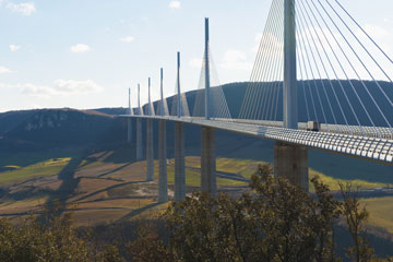
Various combinations of these four technologies allow for numerous bridge designs, ranging from simple beam bridges, arch bridges, truss bridges and suspension bridges to more complex variations, such as the pictured side-spar cable-stayed bridge. For all its 21st century complexity, the side-spar design is based on suspension principles first used some two centuries earlier.
The key differences between these four bridge types comes down to the lengths they can cross in a single span, which is the distance between two bridge supports, the physical braces that connect the bridge to the surface below. Bridge supports may take the form of columns, towers or even the walls of a canyon.
Modern beam bridges, for instance, are likely to span up to 200 feet (60 meters), while modern arch bridges can safely cross 800-1,000 feet (240-300 meters). Suspension bridges are capable of extending from 2,000-7,000 feet (610-2,134 meters).
Regardless of the structure, every bridge must stand strong under the two important forces we’ll talk about next.

Tension and Compression: Two Forces Every Bridge Knows Well
What allows an arch bridge to span greater distances than a beam bridge, or a suspension bridge to stretch over a distance seven times that of an arch bridge? The answer lies in how each bridge type deals with the important forces of compression and tension.

Tension: What happens to a rope during a game of tug-of-war? Correct, it undergoes tension from the two sweaty opposing teams pulling on it. This force also acts on bridge structures, resulting in tensional stress.
Compression: What happens when you push down on a spring and collapse it? That’s right, you compress it, and by squishing it, you shorten its length. Compressional stress, therefore, is the opposite of tensional stress.
Compression and tension are present in all bridges, and as illustrated, they are both capable of damaging part of the bridge as varying load weights and other forces act on the structure. It’s the job of the bridge design to handle these forces without buckling or snapping.
Buckling occurs when compression overcomes an object’s ability to endure that force. Snapping is what happens when tension surpasses an object’s ability to handle the lengthening force.
The best way to deal with these powerful forces is to either dissipate them or transfer them. With dissipation, the design allows the force to be spread out evenly over a greater area, so that no one spot bears the concentrated brunt of it. It’s the difference in, say, eating one chocolate cupcake every day for a week and eating seven cupcakes in a single afternoon.
In transferring force, a design moves stress from an area of weakness to an area of strength. As we’ll dig into on the upcoming pages, different bridges prefer to handle these stressors in different ways.
The Beam Bridge
Bridge building doesn’t get any simpler than this. In order to build a beam bridge (also known as a girder bridge), all you need is a rigid horizontal structure (a beam) and two supports, one at each end, to rest it on. These components directly support the downward weight of the bridge and any traffic traveling over it.
However, in supporting weight, the bream bridge endures both compressional and tensional stress. In order to understand these forces, let’s use a simple model.
If you were to take a two-by-four and lay it across two empty milk crates, you’d have yourself a crude beam bridge. Now if you were to place a heavy weight in the middle of it, the two-by-four would bend. The top side would bend in under the force of compression, and the bottom side would bend out under the force of tension. Add enough weight and the two-by-four would eventually break. The top side would buckle and the bottom side would snap.
Many beam bridges use concrete or steel beams to handle the load. The size of the beam, and in particular the height of the beam, controls the distance that the beam can span. By increasing the height of the beam, the beam has more material to dissipate the tension. To create very tall beams, bridge designers add supporting latticework, or a truss, to the bridge’s beam. This support truss adds rigidity to the existing beam, greatly increasing its ability to dissipate the compression and tension. Once the beam begins to compress, the force spreads through the truss.
Yet even with a truss, a beam bridge is only good for a limited distance. To reach across a greater length, you have to build a bigger truss until you eventually reach the point at which the truss can’t support the bridge’s own weight.

Truss Bridges: Beam Bridges With Braces
Travel around the world, and you’ll encounter dozens of variations on your standard beam bridge. The key differences, however, all come down to the design, location and composition of the truss.
During the early Industrial Revolution, beam bridge construction in the United States was rapidly developing. Engineers gave many different truss designs a whirl in an attempt to perfect it. Their efforts weren’t for naught. Wooden bridges were soon replaced by iron models or wood-and-iron combinations.


All these different truss patterns also factored into how beam bridges were being built. Some takes featured a through truss above the bridge, while others boasted a deck truss beneath the bridge.
A single beam spanning any distance undergoes compression and tension. The very top of the beam gets the most compression, and the very bottom of the beam experiences the most tension. The middle of the beam experiences very little compression or tension. This is why we have I-beams, which provide more material on the tops and bottoms of beams to better handle the forces of compression and tension.
And there’s another reason why a truss is more rigid than a single beam: A truss has the ability to dissipate a load through the truss work. The design of a truss, which is usually a variant of a triangle, creates both a very rigid structure and one that transfers the load from a single point to a considerably wider area.
While truss bridges are largely a product of the Industrial Revolution, our next example, the arch, dates back much further in time. Grab your sword and sandals, because we’re about to go Roman.
The Arch Bridge
After more than 2,000 years of architectural use, the arch continues to feature prominently in bridge designs and with good reason: Its semicircular structure elegantly distributes compression through its entire form and diverts weight onto its two abutments, the components of the bridge that directly take on pressure.
Tensional force in arch bridges, on the other hand is virtually negligible. The natural curve of the arch and its ability to dissipate the force outward greatly reduces the effects of tension on the underside of the arch.
But as with beams and trusses, even the mighty arch can’t outrun physics forever. The greater the degree of curvature (the larger the semicircle of the arch), the greater the effects of tension on the underside of the bridge. Build a big enough arch, and tension will eventually overtake the support structure’s natural strength.
While there’s a fair amount of cosmetic variety in arch bridge construction, the basic structure doesn’t change. There are, for example, Roman, Baroque and Renaissance arches, all of which are architecturally different but structurally the same.
It is the arch itself that gives its namesake bridge its strength. In fact, an arch made of stone doesn’t even need mortar. The ancient Romans built arch bridges and aqueducts that are still standing today. The tricky part, however is building the arch, as the two converging parts of the structure have no structural integrity until they meet in the middle. As such, additional scaffolding or support systems are typically needed.
Modern materials such as steel and prestressed concrete allow us to build far larger arches than the ancient Romans did. Modern arches typically span between 200 and 800 feet (61 and 244 meters), but West Virginia’s New River Gorge Bridge measures an impressive 1,700 feet (518 meters)

The Suspension Bridge
As the name implies, suspension bridges, like the Golden Gate Bridge or Brooklyn Bridge, suspend the roadway by cables, ropes or chains from two tall towers. These towers support the majority of the weight as compression pushes down on the suspension bridge’s deck and then travels up the cables, ropes or chains to transfer compression to the towers. The towers then dissipate the compression directly into the earth.
The supporting cables, on the other hand, receive the bridge’s tension forces. These cables run horizontally between the two far-flung anchorages. Bridge anchorages are essentially solid rock or massive concrete blocks in which the bridge is grounded. Tensional force passes to the anchorages and into the ground.

In addition to the cables, almost all suspension bridges feature a supporting truss system beneath the bridge deck called a deck truss. This helps to stiffen the deck and reduce the tendency of the roadway to sway and ripple.
Suspension bridges can easily cross distances between 2,000 and 7,000 feet (610 and 2,134 meters), enabling them to span distances beyond the scope of other bridge designs. Given the complexity of their design and the materials needed to build them, however, they’re often the most costly bridge option as well.
But not every suspension bridge is an engineering marvel of modern steel. In fact, the earliest ones were made of twisted grass. When Spanish conquistadors made their way into Peru in 1532, they discovered an Incan empire connected by hundreds of suspension bridges, achieving spans of more than 150 feet (46 meters) across deep mountain gorges. Europe, on the other hand, wouldn’t see its first suspension bridge until nearly 300 years later

Of course, suspension bridges made from twisted grass don’t last that long, requiring continual replacement to ensure safe travel across the gap. Today, only one such bridge remains, measuring 90 feet (27 meters) in the Andes.
Cable-Stayed Bridge
At first glance, the cable-stayed bridge may look like just a variant of the suspension bridge, but don’t let their similar towers and hanging roadways fool you. Cable-stayed bridges differ from their suspension predecessors in that they don’t require anchorages, nor do they need two towers. Instead, the cables run from the roadway up to a single tower that alone bears the weight.
The tower of a cable-stayed bridge is responsible for absorbing and dealing with compressional forces. The cables attach to the roadway in various ways. For example, in a radial pattern, cables extend from several points on the road to a single point at the tower, like numerous fishing lines attached to a single pole. In a parallel pattern, the cables attach to both the roadway and the tower at several separate points.

Engineers constructed the first cable-stayed bridges in Europe following the close of World War II, but the basic design dates back to the 16th century and Croatian inventor Faust Vrancic. A contemporary of astronomers Tycho Brache and Johannes Kepler, Vrancic produced the first known sketch of a cable-stayed bridge in his book “Machinae Novae.”
Today, cable-stayed bridges are a popular choice as they offer all the advantages of a suspension bridge but at a lesser cost for spans of 500 to 2,800 feet (152 to 853 meters). They require less steel cable, are faster to build and incorporate more precast concrete sections.
Not all bridges requires great hunks of steel and concrete though. Sometimes a tree root or two will do the trick.
The Living Bridges
While the first bridges were likely nothing short of logs toppled over creeks, most of humanity’s bridge-building legacy is a story of artificial structures crafted out of the elements. We can find, however, one of the most striking exceptions to this rule in the Meghalaya region of northern India.
During monsoon season, locals here endure some of the wettest conditions on Earth, and rising floodwaters cut the land into isolated fragments. Build a bridge out of woven vines or hewn boards and the rainforest moisture will inevitably turn it into compost. As you can see from the photo, the local people developed a rather elegant solution to the problem: They grow their bridges out of natural vegetation. In doing so, they turn a large portion of the bridge maintenance duties over to the bridge itself.
Building a living bridge takes patience, of course. The local villagers plan their constructions a decade or more in advance. The War-Khasis people, for instance, create root-guidance systems from the hollowed halves of old betel nut tree trunks to direct strangler fig roots in the desired direction. They simply direct the roots out over a creek or river, spanning it, and only allow the roots to dive into the earth on the opposite bank. The larger living bridges boast lengths of up to 100 feet (30 meters), can bear the weight of 50 people and can last upward of 500 years

So far, we’ve touched on the two most important forces in bridge design: compression and tension. Yet dozens of additional forces also affect the way bridges work. These forces are usually specific to a particular location or design.
Torsion, for instance, is a particular concern for engineers designing suspension bridges. It occurs when high wind causes the suspended roadway to rotate and twist like a rolling wave. As we’ll explore on the next page, Washington’s Tacoma Narrows Bridge sustained damage from torsion, which was, in turn, caused by another powerful physical force
The natural shape of arch bridges and the truss structure on beam bridges protects them from this force. Suspension bridge engineers, on the other hand, have turned to deck-stiffening trusses that, as in the case of beam bridges, effectively eliminate the effects of torsion.
In suspension bridges of extreme length, however, the deck truss alone isn’t enough protection. Engineers conduct wind tunnel tests on models to determine the bridge’s resistance to torsional movements. Armed with this data, they employ aerodynamic truss structures and diagonal suspender cables to mitigate the effects of torsion.
Shear: Shear stress occurs when two fastened structures (or two parts of a single structure) are forced in opposite directions. If left unchecked, the shear force can literally rip bridge materials in half. A simple example of shear force would be to drive a long stake halfway into the ground and then apply lateral force against the side of the upper portion of the stake. With sufficient pressure, you’d be able to snap the stake in half. This is shear force in action.
More Bridge Forces: Resonance
You can think of resonance as the vibrational equivalence of a snowball rolling down a hill and becoming an avalanche. It begins as a relatively small, periodic stimulus of a mechanical system, such as wind buffeting a bridge. These vibrations, however, are more or less in harmony with the bridge’s natural vibrations. If unchecked, the vibration can increase drastically, sending destructive, resonant vibrations traveling through a bridge in the form of torsional waves.
The most noteworthy example of resonance occurred in 1940, when resonant vibrations destroyed the Tacoma Narrows Bridge in Washington. The incident was especially shocking at the time as the structure was designed to withstand winds of up to 120 miles (193 kilometers) per hour and collapsed in a mere 40-mile (64-kilometer) wind.
Close examination of the situation suggested that the bridge’s deck-stiffening truss was insufficient for the span, but this alone couldn’t bring such a structure down. As it turned out, the wind that day was at just the right speed and hit the bridge at just the right angle to set off the deadly vibration. Continued winds increased the vibrations until the waves grew so large and violent that they broke the bridge apart. The effect is similar to that of a singer shattering a glass with her voice.
Wind isn’t the only potential threat, however. When an army marches across a bridge, the soldiers often “break step” so that their rhythmic marching will not start resonating throughout the bridge. A sufficiently large army marching at just the right cadence could set the deadly vibration into motion.
In order to mitigate fully the resonance effect in a bridge, engineers incorporate dampeners into the bridge design to interrupt the resonant waves and prevent them from growing.
Another way to halt resonance is to give it less room to run wild. If a bridge boasts a solid roadway, then a resonant wave can easily travel the length of the bridge and wreak havoc. But if a bridge roadway is made up of different sections with overlapping plates, then the movement of one section merely transfers to another via the plates, generating friction. The trick is to create enough friction to change the frequency of the resonant wave. Changing the frequency prevents the wave from building.

Weather, Destroyer of Bridges
While wind can certainly induce destructive resonant waves, weather as a whole unleashes a host of destructive assaults on the bridges we build. In fact, the relentless work of rain, ice, wind and salt will inevitably bring down any bridge that humans can erect.
Bridge designers have learned their craft by studying the failures of the past. Iron has replaced wood, and steel has replaced iron. Prestressed concrete now plays a vital role in the construction of highway bridges. Each new material or design technique builds off the lessons of the past. Torsion, resonance and poor aerodynamic designs have all led to bridge failures, but engineers continually bounce back with innovations to solve design problems.
Weather, however, is a patient and unpredictable adversary. Cases of weather-related bridge failure tend to outnumber those of design-related failures. This trend can only suggest that we have yet to come up with an effective solution. To this day, no specific construction material or bridge design can eliminate or even mitigate these forces. After all, we’re talking about the same forces that degrade whole mountain ranges and forge deep chasms in the earth. By comparison, a man-made bridge is nothing.
As with the ancient Incan suspension bridges, the only deterrent is continual preventive maintenance.
Span the gap between this page and the next to find out even more about bridges.
Sources
- Blockley, David. “Bridges” Oxford University Press. 2010.
- “Build a Bridge.” NOVA. October 2000. (May 17, 2011)http://www.pbs.org/wgbh/nova/bridge/build.html
- Foer, Joshua. “The Last Incan Grass Bridge.” Slate. Feb. 22, 2011. (May 17, 2011)http://www.slate.com/id/2286002/
- Merchant, Brian. “Living Bridges in India Have Grown for 500 Years.” TreeHugger.com. Sept. 28, 2010. (May 17, 2011)http://www.treehugger.com/files/2010/09/living-bridges-india-grown-500-years-pics.php
- “Rivers.” Human Planet Explorer. 2011 (May 17, 2011)http://www.bbc.co.uk/nature/humanplanetexplorer/environments/rivers
- Wilford, John Noble. “How the Inca Leapt Canyons.” New York Times. May 8, 2007. (May 17, 2011)http://www.nytimes.com/2007/05/08/science/08bridg.html
